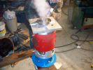
Flywheel adapter is on!3779 viewsCooling it down after pressing it on to the shaft. (more like setting it on, and tapping it gently down.)
|
|
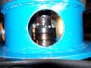
Bolting coupler together3750 viewsWe hadn't realized just how difficult it was going to be to tighten the bolts holding the coupler together. It was really awkward and hard. Took 2 people. (one turning the motor, the other holding the allen wrench.)
This was compouned when we discovered another alignment problem. Turns out that the end bells of the Impulse 9 motors aren't that accurately machine. We had a 10-20 thousandths variance between them that we had to shim.
|
|
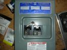
Mechanical link between Breakers3726 viewsThis shows how I made it so that only 1 of the 2 power inlet breakers can be ON at a time.
Both can be off, but only 1 can be ON.
|
|
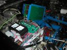
Control Wiring3691 viewsThis is the main control wiring for the EV conversion. It has the Z2K Hairball, and all the various relays, meters, fuses, etc..
The 2 meters are AC Amps and Volts for the PFC-50 charger.
|
|
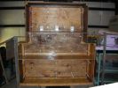
Battery Hold Downs3684 viewsAll the battery hold down posts are in place. These are 3/8 allthread into the flange nuts on the bottom of the box.
There are posts on either side of each pair of batteries.
A square bar will be across the full width of the box, bolted to all the posts in that row.
|
|
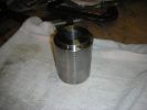
Finished Coupler3679 viewsThe finished coupler. (Well, I did have to have 2 keyways cut into it, and drill some holes for set screws after this.)
|
|
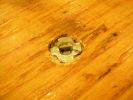
Battery Hold Down Post Nuts3650 viewsI put a little weld in the bottom of each hold down flange nut so that the post can't be screwed in too far.
This is to prevent it being screwed down through the covering fiberglass at a later date.
|
|
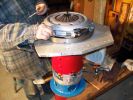
Flywheel and cluth mounted3613 viewsBolted things together, bolted on the flywheel and clutch assemblies.
|
|
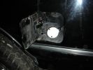
120v, 20A charge port3601 viewsThis is the 120V, 20A charge port.
|
|
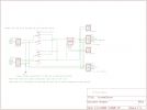
AC Power Schematic3582 viewsThis is the schematic for the AC inlet power.
There are both 120V (standard 20A plug) and 240V (CS6375) AC power inlets.
Each has a separate breaker, and only 1 breaker can be ON at a time due to a mechanical interlock.
|
|
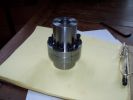
Finished and drilled couplers3464 viewsThis is the finished coupler assembly with all the screws that will be used to hold them together.
|
|
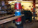
Putting them together3433 viewsBoth motors together! Bolted to the motor-motor mount.
|
|
| 118 files on 10 page(s) |
 |
 |
 |
5 |  |
 |
 |
 |
|